Technologies

TFT LCD
TFT LCD (Thin-Film Transistor Liquid Crystal Display) is a type of active matrix, non-emissive display. TFT requires a light source in order to be legible, and/or reflects surrounding light in order for the content to be visible to the human eye. TFT utilizes thin-film transistors to control voltage, thus modulating the light passing through the color filter to display on the panel surface.
TFT LCD vs OLED Display
Strengths
Weaknesses
- Lower Cost
- Longer Lifetime (inorganic material)
- Higher Peak Brightness
- Higher Resolution Density
- Limited for Flexible, Free-Form Applications
- High Cost for High Color Gamut and Contrast Ratio (e.g. with Quantum Dot, Mini-LED Backlight)
Our Strategies
- Diversified product portfolio with normal and high brightness options at various sizes
- Total solution to achieve the best performance at the module/touchscreen level
BOE Technology Highlights
- ADSDS (Advanced Super Dimension Switch) technology (Normally black) with wide viewing angles, quick response time, transmittance, brightness, and contrast ratio
- BD Dual-Cell HDR technology to achieve OLED level optical performance at a competitive price
Types and Market Trends
| Criteria | Type | Market demand |
|---|---|---|
| By Transmission Mode | Transmissive | -- |
| Transflective | -- | |
| Reflective | Niche | |
| By Switching Mode | Normally White: TN | -- |
| Normally Black (Wide viewing technologies): (BOE)ADSDS/FFS/IPS/MVA | Increasing | |
| By TFT material | a-Si TFT | -- |
| LTPS | Increasing | |
| Oxide TFT | Specialty |
1“BOE ADSDS Ultra Hard Screen Technology.” High-Definition Display, Display, Intelligent System, Health Services, BOE, BOE Official Website, www.boe.com/en/cxkj/boecx/dynamic/1393.html.
How LCD works
As in its name, Liquid crystal displays utilize Liquid Crystals, which exhibit both characteristics of solid and liquid. Applying an electric field can change LC molecular alignment temporarily, and thus modulate the polarization of light passing through. LCDs don’t emit light themselves so they need other light sources.
The optical configuration of an LCD, often referred to as a “sandwich” structure, typically includes a) a front polarizer or analyzer; b) a back polarizer, cross-positioned to the front one in terms of polarization; and c) a liquid crystal layer in between.
Depending on transmission modes of the “light modulator”, LCDs can be divided into three categories: transmissive, reflective, and transflective mode, as illustrated below. Note that back polarizers in these LCDs are transmissive, reflective, transflective types accordingly, while front polarizers are always transmissive to let the modulated light through.
Reflective LCDs utilize ambient light from a front source, usually the environmental light. Whereas transmissive displays rely on LED backlights to illuminate the surface. Featuring a combination of both reflective and transmissive characteristics, a transflective LCD can take advantage of both environmental ambient light and LED backlight at the same time.
All three transmission modes are used in passive LCDs, whereas most TFT LCDs are transmissive types.
How TFT LCD works
Thin-Film Transistor Liquid Crystal Displays use thin-film transistors to control the voltage applied to the liquid crystal layer at a sub-pixel level. The structure of TFT LCDs consists of a TFT “sandwich” and a BLU (Backlight Unit). A typical configuration is shown in the schematic diagram below.

Schematic diagram of an LCD
Firstly, between the back and front polarizers, TFT LCD cells are made with two glass substrates – one for color filters, the other for a TFT array – and a liquid crystal layer sandwiched in between.
Secondly, BLU (Backlight Unit) usually consists of three components: BEF (Brightness Enhancement Film), DBEF (Dual Brightness Enhancement Film), and LGP (Light Guide Plate).
For normally black TFT LCDs, if we follow along a piece of light setting off from its backlight source, it will be a) guided uniformly by LGP; b) reflected and enhanced by BEF and DBEF; c) polarized by the back polarizer; d) polarization changed by twisted LC under the voltage applied by TFT arrays; e) “tinted” red/green/blue by corresponding color filter of the subpixel; f) let through the front polarizer by matched polarization; and g) finally, it will reach the surface and appears in viewer’s eyes.
For normally white panels, process d) will be the opposite – known as the polarization rotation effect, light is twisted in a voltage-off stage and can pass through the front polarizer by default, thus displaying white normally. However, when the voltage applied increases, this polarization rotation effect would be gradually diminished. And the light would not be able to pass through the front polarizer anymore without changing its polarization. In this way, certain pixels will appear in different colors.
Normally black LCDs have higher contrast and wider viewing angles without grayscale inversion phenomenon compared to their normally white relatives. And whether TFT LCDs are normally black or white depends on their LC switching mode:
- Normally white mode
- (1) twisted nematic (TN) mode
- Normally black modes
- (2) vertical alignment (VA) mode;
- (3) in-plane switching (IPS) mode;
- (4) fringe-field switching (FFS) mode; and
- (5) BOE’s patented ADSDS (Advanced Super Dimension Switch) mode
2 Chen, HW., Lee, JH., Lin, BY. et al. Liquid crystal display and organic light-emitting diode display: present status and future perspectives. Light Sci Appl 7, 17168 (2018). https://doi.org/10.1038/lsa.2017.168

Schematic diagram of the (a) TN mode, (b) VA mode, (c) FFS mode, and (d) IPS mode. *LC orientations shown are under applied voltages. C/F stands for the color filter.
As previously mentioned, TN mode functions with the polarization rotation effect. Under traditional TN/VA display mode, the liquid crystal molecules are vertically arranged, with a relatively narrow visual angle. When an external force is exerted on the screen, the liquid crystal molecular structure will sink in a herringbone pattern to slowly recover – a pattern called vertical alignment. Therefore, an evident “water ripple” usually appears when the display surface is touched and impacts the user experience. In comparison, the VA mode provides higher contrast. And MVA (multi-domain vertical alignment) is an upgraded version of VA with improved viewing angles.
Under IPS mode, the LC directors are horizontally (homogeneously) aligned, which makes them free from ripple effects when made into touch panels. The drawback is lower transmittance, especially for LCs in a “dead zone” close to electrodes.
In an FFS cell, LC molecules rotate in both vertical and horizontal dimensions, enabling excellent viewing angles, high transmittance, low driving voltage/power consumptions, and high contrast ratio.
3 Yang DK, Wu ST. Fundamentals of Liquid Crystal Devices. 2nd edition. New York, USA: John Wiley & Sons. 2014.
4 BOE ADSDS Ultra Hard screen Technology, Restoring Real and Beautiful Life. 2020 BOE Technology Group Co., Ltd. Retrieved December 01, 2020, from https://www.boe.com/en/cxkj/boecx/boecxxqy/dynamic/pecbbd751.html
BOE ADSDS Ultra Hard screen Technology
As one of the world’s leading Ultra Hard screen technologies, the unique ADSDS (Advanced Super Dimension Switch) technology owned by BOE provides higher transmittance, brightness, and contrast ratio, as well as wide viewing angles of about 90° at all directions to present vivid images. Meanwhile, ADSDS TFT LCD features low power consumption and is thus eco-friendly.
The technology has been widely applied in smartphones, tablet PCs, laptops, monitors, and TVs.
In ADSDS mode, the liquid crystal molecules are arranged horizontally, with much wider viewing angles. When an external force is exerted on the screen, liquid crystal molecular structures only sinks slightly, but the overall structure remains horizontal, without producing any water ripple.
Furthermore, BOE’s ADSDS technology has overcome the barrier of low transmittance commonly seen in other wide viewing technologies, such as IPS, achieving high transmittance with wide viewing angles.
Pros & Cons of Wide Viewing TFT LCD Technologies
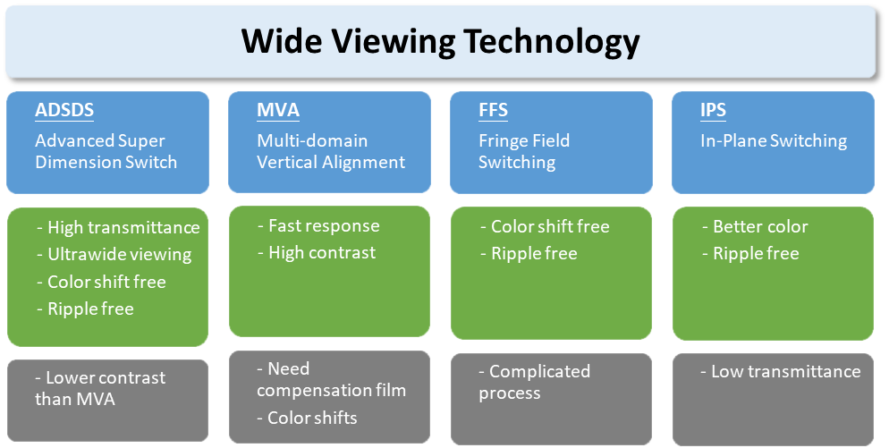
As described before, the strengths and weaknesses of wide viewing TFT LCD technologies based on four switching modes are summarized below:

Comparison Table of Wide Viewing Technologies
When choosing a display for wide viewing applications based on the switching mode, ADSDS generally provides the best value when there is no specific requirement for ultra-high contrast (>1200:1), in which case MVA could be a better option.
Pros & Cons of TFT Materials
There are three major types of materials for TFTs as compared in the table below:
Types of Active Matrix LCDs by Material
| Type | LTPS TFT | Oxide TFT | a-Si TFT |
|---|---|---|---|
| Material | Polycrystalline Silicon on glass | Oxide semiconductor (IGZO) on glass | Amorphous Silicon on glass |
| Thickness (Board only) | 0.2-0.3mm (Small/medium area), 0.5-0.7mm (Large area) | 0.5-0.7mm | 0.5-0.7mm |
| Pros |
|
|
|
| Cons |
|
|
|
While amorphous silicon TFTs represents the most market share with its competitive price and mature technical know-how in the industry, LTPS (Low-temperature polycrystalline silicon) TFTs are widely used in automotive, mobile devices, and other displays with high requirements for optical performance and a slim, borderless design.
Oxide TFTs are stable and easy to produce even under room temperature. Their price point is between LTPS’s and a-Si’s. Oxide TFT is still relatively new to the market targeting specialty markets.
Applications
TFT LCDs have been serving as the backbone of the display industry for more than a decade. With a wide range of mature technologies and industrialization, they deliver highly reliable solutions at a low price-performance ratio. Nowadays, TFT LCD is still dominating consumer markets (e.g. TVs, laptops, and monitors), aeronautic/marine/automotive displays, medical and industrial HMIs (human-machine interfaces), and other display applications.

TFT at home (phone, TV, tablet, laptop, white goods, IoT products, etc.)

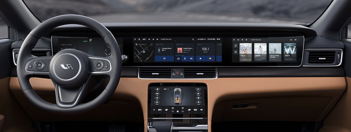
TFT for automotive/marine/aviation
Editor: Charis Chen


